While computer aided drafting (CAD) offers a more plastic interface for rendering linework, the current practice of prescribing weights to architectural lines still bears a strong resemblance to the use of a fixed set of Rapidograph pens. Digital line data can be divided into an array of layers or objects which can be given a unique lineweight, but each line still maintains a uniform width along its length. Despite the abundance of parametric features in digital modelling software, no clear CAD protocol exists for rendering a stroke with a controlled, variable width.
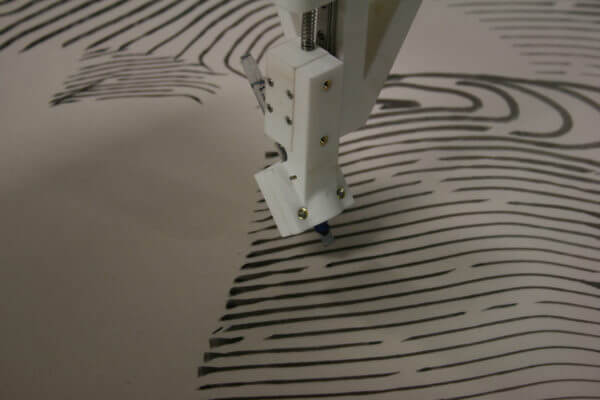
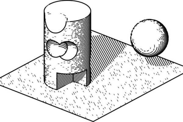
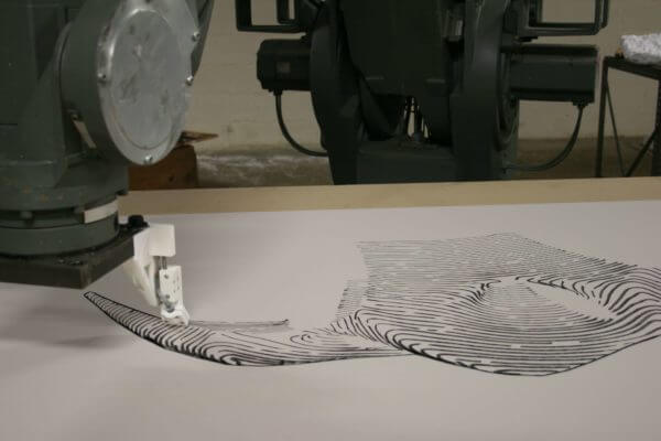
Variable Information Lineweights is a work-in-progress method for rendering three dimensional models with nonuniform lineweights that are dynamically linked to datasets of object properties (such as light exposure, depth, or structure). At present, the software is used to directly output drawing code to an industrial robot (ABB IRB 6400), but the basic premise can be applied to a number of rendering strategies: curves are stored in a vector format where each vertex is paired with a corresponding lineweight.
The relatively modest software (~2000 lines) is written in Processing, and creates a link between geometry data (from Rhino) and surface attributes—providing a visual interface for tuning the relationship between these parameters and the rendered lines.(Fig 2) Geometry data is divided into layers in Rhino, and exported with a custom descriptor document generated in Grasshopper. Once imported into the Processing software, each layer is assigned an automatically-generated control panel, which provides a series of sliders and editable bezier-based mapping functions. These sliders control basic parameters such as minimum and maximum line width, and more advanced parameters, such as the ratio of influence of various attributes over lineweight or the probability that a given vertex is rendered at all. For example, a layer might be set up such that the foreground is more heavily influenced by scene lighting, while the background is more heavily influenced by the distance between the object and the camera or viewer. The attributes which determine lineweights can be loaded and correlated with the vertex data in a number of ways: either as a list of values, an aligned black and white image, or directly from the 3D information.
Once the shading strategy is tuned and selected, the software outputs robot code directly. This process involves optimizing the drawing for robot motion by reducing unnecessary vertices, sorting and reversing curve direction to minimize transfer distances (and drawing time), and adding routines for avoiding robot joint errors (as most industrial robots cannot spin their last axis indefinitely, certain long curves with significant rotations require that the robot lift up the pen, reset the rotation of the exceeding axis, and then continue with the line).
The robot is equipped with a custom spring-loaded pen holder which accommodates a variety of pen and marker types. A single calligraphy pen (6 mm Pilot Parallel) is used in these sample images, which allows for a stroke-width range of .065-6 mm depending on rotation.
The included images represent the first-stage tests of this technique, which remains in development. While far from streamlined, the process enables fast prototyping of drawings with various types of data embedded into the linework, and an intuitive control panel for editing the influence of each data type over the final image.
–From Johns, Ryan Luke. “Variable Information Lineweights” In: Allen L, Pearson L (eds) Drawing Futures. UCL Press, 2016.


